IF requiring Greater insight of AVR current development by others...
do check these forum....
http://www.avrfreaks.net
http://avr.15.forumer.com/
http://www.nabble.com/AVR-f2008.html
Saturday, May 10, 2008
Some AVR Forum (good ones)
Softwares required for AVR beginners....
<<
1) AVR Dude
available all versions at http://download.savannah.gnu.org/releases/avrdude/
2) Pony Programmer
latest version :: http://downloads.sourceforge.net/ponyprog/PonyProg_V207c.zip
or available at http://www.lancos.com/ppwin95.html
3) Win AVR ( required with AVR studio )
http://winavr.sourceforge.net/download.html
4) AVR Studio ......currently available at
http://www.atmel.com/dyn/Products/tools_card.asp?tool_id=2725
or search on GOOGLE or check www.atmel.com
available at http://www.cadsoftusa.com/download.htm
After release of AVRStudio4 there is possible to integrate AVR-GCC compiler in to it. As you know AVRstudio is a powerful tool which has assembler compiler- debugger, programmer, etc. Integration of AVR-GCC to it makes this tool much more powerful and more complete playground for developer. Plugin which is built in AVRStudio detects AVR-GCC compiler by it self, so you don’t have to bother how to tie them together. And here we go - full set of good tools comparable to commercial. Convenient user interface, automatic makefile generation, visual debugging by watching processors register, or even you can flash the chip.
DO add comments for further additions or deletions in the current post....

Thursday, May 8, 2008
Whats next......(to be added soon)
To be added soon :-
Hardware & embedded...
Driving DC motor using AVR & 8051
Stepper motor interfacing using AVR & 8051
Interfacing ADC , DAC (8051)
Use of inbuilt ADC of AVR
Serial communication using 8051
Serial communication using AVR
Using AVR as DTMF receiver
Interfacing external DTMF reciever with 8051
Parallel processing using AVR / 8051
Triple modular redundancy using AVR / 8051
VLSI
wanna know the effect of shrinking length of MOS transistors...effects on ...Ballistic mosfet ...
MATLAB :: language of Technical computing..
implementation of various theorems & mathematical formulae for the beginners
sound processing & similar applications
image processing & similar applications
interfacing to external hardware using MATLAB
serial communication between 2 PC using MATLAB
MATLAB GUI implementation of various kinds...
LINUX (on http://learncomputersecrets.blogspot.com )
GUI desktop application implementation in linux
IEEE Std 1003.1-1990 POSIX -( portable operating system interface for unix ) -- implementation in linux GCC compiler...for serial communication using LINUX (detailed description)
GRUB details & bootloader options
Playing with GRUB
Visual C++ (on http://learncomputersecrets.blogspot.com)
Parallel port programming
( Without using any DEVICE Drivers access Parallel port in windows XP)
Serial port programming
Image capture from any external WDM device installed on PC
How to start image capture on getting any interrupt
from external device through serial port or parallel port (ie. integrating 1 & 2 & 3 )
Visual C++ object model...for implementation of various constructs used to make multiple dialog application ( using different methods)
Database connectivity by various methods..to different servers..
JAVE Netbeans (on http://learncomputersecrets.blogspot.com)
How to create multiple dialog application with minimum efforts...
How to connect to database to retrieve & store data ( using MS ACCESS , SQL server , ORACLE ,other database softwares)
General knowledge concepts for embedded & computer beginners..
How to learn any computer language in some days with best implementation constructs.
USB POWER for circuits.....
Using old conventional methods to get the power for
5V circuits requiring pc interface
or
even if PC is available...
USE USB connector with wire to get 5V supply (regulated) for the circuits....
LDO (low dropout regulator) might be required...but it will give the minimum losses in terms of power..(least dropout)
USB connectors
Jack connector


Pinout description (for both mini usb & usb)
USB
| Pin one side | Signal | Description | Pin other side |
| 1 | USB Vcc (Vbus) | usually RED, wire should be 20-28 AWG | 1 |
| 2 | USB Data - | usually WHITE, wire should be 28 AWG | 2 |
| 3 | USB Data + | usually GREEN, wire should be 28 AWG | 3 |
| 4 | GND | usually BLACK, wire should be 20-28 AWG | 4 |
USB D+ and D- are twisted in cable. Outer shell is made of copper braid and aluminium shield.
MINI USB| Pin | Name | Cable color | Description |
|---|---|---|---|
| 1 | VCC | Red | +5 VDC |
| 2 | D- | White | Data - |
| 3 | D+ | Green | Data + |
| X | ID | May be N/C, GND or used as an attached device presence indicator (shorted to GND with resistor) | |
| 4 | GND | Black | Ground |
USB DETAILS
USB
The Universal Serial Bus is host controlled and there can be only one host per bus. An USB system consist of a host controller and multiple devices connected in a tree-like fashion using special hub devices. Hubs may be cascaded, up to 5 levels. Up to 127 devices may be connected to a single host controller. USB interface aimed to remove the need for adding expansion cards into the computer's PCI or PCI-E bus, and improve plug-and-play capabilities by allowing devices to be hot swapped or added to the system without rebooting the computer. When the new device first plugs in, the host enumerates it and loads the device driver necessary to run it. The loading of the appropriate driver is done using a PID/VID (Product ID/Vendor ID) combination supplied by attached hardware. The USB host controllers has their own specifications: UHCI (Universal Host Controller Interface) and OHCI (Open Host Controller Interface) are used with USB 1.1, EHCI (Enhanced Host Controller Interface) is used with USB 2.0
| Pin | Name | Cable color | Description |
|---|---|---|---|
| 1 | VCC | Red | +5 VDC |
| 2 | D- | White | Data - |
| 3 | D+ | Green | Data + |
| 4 | GND | Black | Ground |
USB pinout signals
USB is a serial bus. It uses 4 shielded wires: two for power (+5v & GND) and two for differential data signals (labelled as D+ and D- in pinout). NRZI (Non Return to Zero Invert) encoding scheme used to send data with a sync field to synchronise the host and receiver clocks. In USB data cable Data+ and Data- signals are transmitted on a twisted pair. No termination needed. Half-duplex differential signaling helps to combat the effects of electromagnetic noise on longer lines. Contrary to popular belief, D+ and D- operate together; they are not separate simplex connections.
USB transfer modes
Univeral serial bus supports Control, Interrupt, Bulk and Isochronous transfer modes.
USB transfer rates: Low Speed, Full Speed, Hi-speed.
USB supports three data rates: Low Speed (1.5 Mbit per second) that is mostly used for Human Input Devices (HID) such as keyboards, mice, joysticks and often the buttons on higher speed devices such as printers or scanners; Full Speed (12 Mbit per second) which is widely supported by USB hubs, assumes that devices divide the USB bandwidth between them in a first-come first-serve basis - it"s easy to run out of bandwidth with several devices; Hi-Speed (480 Mbit per second) was added in USB 2.0 specification. Not all USB 2.0 devices are Hi-Speed. A USB device must indicate its speed by pulling either the D+ or D- line high to 3.3 volts. These pull up resistors at the device end will also be used by the host or hub to detect the presence of a device connected to its port. Without a pull up resistor, USB assumes there is nothing connected to the bus.
In order to help user to identify maximum speed of device, USB device often specify it's speed on it's cover with one of USB special marketing logos.
USB Hi-speed devices
Hi-Speed devices should fall back to the slower data rate of Full Speed when plugged into a Full Speed hub. Hi-Speed hubs have a special function called the Transaction Translator that segregates Full Speed and Low Speed bus traffic from Hi-Speed traffic.
USB powered devices
The USB connector provides a single 5 volt wire from which connected USB devices may power themselves. A given segment of the bus is specified to deliver up to 500 mA. This is often enough to power several devices, although this budget must be shared among all devices downstream of an unpowered hub. A bus-powered device may use as much of that power as allowed by the port it is plugged into. Bus-powered hubs can continue to distribute the bus provided power to connected devices but the USB specification only allows for a single level of bus-powered devices from a bus-powered hub. This disallows connection of a bus-powered hub to another bus-powered hub. Many hubs include external power supplies which will power devices connected through them without taking power from the bus. Devices that need more than 500 mA or higher than 5 volts must provide their own power. When USB devices (including hubs) are first connected they are interrogated by the host controller, which enquires of each their maximum power requirements. However, seems that any load connected to USB port may be treated by operating system as device. The host operating system typically keeps track of the power requirements of the USB network and may warn the computer's operator when a given segment requires more power than is available and may shut down devices in order to keep power consumption within the available resource.
USB power usage:
Bus-powered hubs: Draw Max 100 mA at power up and 500 mA normally.
Self-powered hubs: Draw Max 100 mA, must supply 500 mA to each port.
Low power, bus-powered functions: Draw Max 100 mA.
High power, bus-powered functions: Self-powered hubs: Draw Max 100 mA, must supply 500 mA to each port.
Self-powered functions: Draw Max 100 mA.
Suspended device: Max 0.5 mA
USB voltage:
Supplied voltage by a host or a powered hub ports is between 4.75 V and 5.25 V. Maximum voltage drop for bus-powered hubs is 0.35 V from it's host or hub to the hubs output port. All hubs and functions must be able to send configuration data at 4.4 V, but only low-power functions need to be working at this voltage. Normal operational voltage for functions is minimum 4.75 V.
USB cable shielding:
Shield should only be connected to Ground at the host. No device should connect Shield to Ground.
USB cable wires:
Shielded:
Data: 28 AWG twisted
Power: 28 AWG - 20 AWG non-twisted
Non-shielded:
Data: 28 AWG non-twisted
Power: 28 AWG - 20 AWG non-twisted
MINI USB
USB pinout signals
USB is a serial bus. It uses 4 shielded wires: two for power (+5v & GND) and two for differential data signals (labelled as D+ and D- in pinout). NRZI (Non Return to Zero Invert) encoding scheme used to send data with a sync field to synchronise the host and receiver clocks. In USB data cable Data+ and Data- signals are transmitted on a twisted pair. No termination needed. Half-duplex differential signaling helps to combat the effects of electromagnetic noise on longer lines. Contrary to popular belief, D+ and D- operate together; they are not separate simplex connections.
USB cable wires:
Shielded:
Data: 28AWG twisted
Power: 28AWG - 20AWG non-twisted
Non-shielded:
Data: 28AWG non-twisted
Power: 28AWG - 20AWG non-twisted
LED case light....
(Building an LED caselight - Originally published 2001 in Atomic: Maximum Power Computing)
LED primer
LEDs, of any size or shape, are quite easy things to work with once you know a few basic things about them, and about electricity.
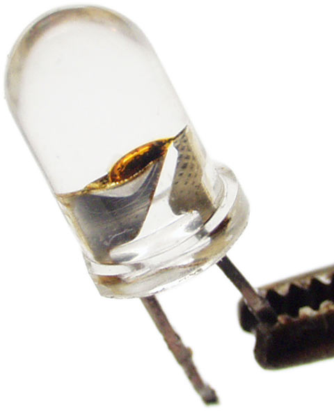
LEDs are, basically, a bit like normal light bulbs. You pass electricity through them and they glow. If you pass too much electricity through them, they die. There are some important differences between LEDs and incandescent lamps, though.
First, LEDs are diodes, so they have polarity; they only work one way. Ordinary LEDs (not Luxeons, or tiny surface mount LEDs) have a long leg and a short leg, as they come from the factory. The long leg of an LED is the positive one. If you connect the thing backwards, it won't do anything. It won't be hurt, either, though, unless you apply rather more reverse voltage than the LED normally runs from. Anyone who's assembled a computer and connected the case LED plugs backwards will know this already.
Second, LEDs need some resistance in series with them, either as part of the power source (if it's a small battery, for instance), or as a separate resistor. This is because LEDs have a death wish.
Incandescent lamp filaments have a positive temperature coefficient of resistance; when they get hotter, their resistance rises. They get very hot in normal use, and their resistance is much higher then than when they're turned off. Like, more than ten times as high.
LEDs aren't like that. They've got a negative temperature coefficient of resistance; the hotter they get, the lower their resistance becomes. And they warm up in normal operation - they're not magic 100% efficient electricity-to-light converters, but waste some power as heat, just like everything else.
If an LED is already passing enough current that a bit more power dissipation will kill it, and there's nothing - like a series resistor - to stop the heat-related resistance drop from allowing the LED to dissipate more power, you've got a situation called "thermal runaway", and your LED is not long for this world.
Overdrive an LED relatively gently and it'll briefly emit colours rather higher in the spectrum than the one it's meant to produce, and then die, with a very small sad sizzling noise. The thing you are left with after this may be referred to as a "friode".
If you overdrive an LED brutally, it'll still end up as a friode, but it will in the interim briefly function as an SED, or Smoke Emitting Diode.
Ex-SEDs are always open circuit - they don't pass any current - but more gently killed LEDs can end up short-circuited, which is worse. When a shorted LED is in a series string with other LEDs, they get to see all of the voltage that was meant to supply the whole string. This, of course, accelerates their own death.
Amps, volts and resistors
With reasonable heat-sinking, you can push more than 50 milliamps (mA, thousandths of an ampere) through modern high intensity 5mm LEDs, and a lot more through a Luxeon Star. Luxeon lamps, except for the bare-LED "emitter" version, all come attached to a small heat-sink circuit board. Ordinary LEDs are encapsulated in their epoxy lens, which is a good thermal insulator; their metal legs can conduct some heat away, but that's all they've got. Hence, less heat dissipation, even if you solder them to big fat conductive wires.
The rated safe-at-any-temperature current for 5mm LEDs is typically less than 30mA; 20mA is the usual current you'll see on the spec sheet.
That spec sheet will also tell you the nominal forward voltage for a given LED, which'll be around 2.0 volts for red and orange LEDs, around 2.2V for yellow and green ones, and substantially higher for the more expensive blue LEDs - they're generally rated at 3.0 to 3.6V.
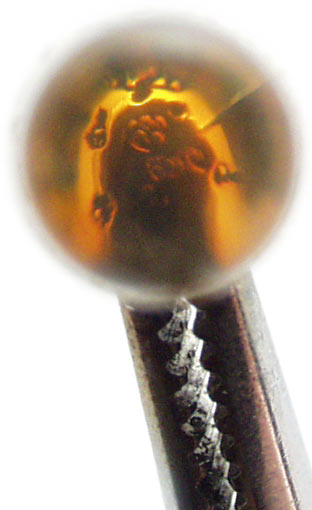
White LEDs have similar ratings to blue ones, because they actually are blue ones - they have a phosphor layer over a blue LED die, which absorbs most of the blue and emits a range of other frequencies to give you a broad-spectrum white result.
You can wire identical LEDs in series or in parallel. If you're making a large LED array, you'll probably be doing both.
A parallel-wired array of LEDs - with each LED connected directly to the same power supply as if it were wired up by itself, and no electrons having to flow through one LED to get to the next - behaves, electrically, like one big unit with the same voltage drop as a single LED, but the current draw of all of the LEDs in the array put together. So, for instance, six 2V/20mA red LEDs wired in parallel will run from 2V, but will draw 120mA.
The brighter Luxeon Star LEDs have lower voltage requirements; leave a white Luxeon Star LED with just its standard heat sink, so it can get quite warm as the voltage rises, and you'll get 300mA current draw from little more than 3V - and the current can still rise another 50mA before you'll exceed the LED's specified limits.
Six of these LEDs in parallel will still run from 3V, but will draw 1.8 amps.
A series chain of LEDs behaves, electrically, like one unit with the same current draw as a single LED, but the voltage drop of all of the LEDs in the chain put together. So, for instance, six 2V red LEDs in a chain can be run from 12 volts. And six white 3V/300mA Luxeons in series will need an 18V supply, but still draw 300mA.
You can wire series LED arrays in parallel with each other, too. Take two chains, each containing six 2V 20mA LEDs, and connect them in parallel, and the resultant series-parallel array will run from 12V, and draw 40mA. Two of the abovementioned six-Luxeon chains put in parallel with each other will run from 18V and draw 600mA.
Because LEDs change resistance with temperature, though (see the "LED primer" box), you can't just connect a "12 volt" LED array to any old 12V power supply. Like, for instance, the 12 volt rail from your computer PSU.
Well, you can - if the LEDs really do start out drawing only 20mA, then they might well not get hot enough to kill themselves. But it's still not a great idea.
To take the edge off the thermal runaway problem, you use an in-line resistor, and a power supply with a higher voltage than the array wants. Resistors do not significantly change in value with the amount of current flowing through them. The resistor eats some of the volts, and damps the runaway by a varying amount, depending on its resistance value compared with the effective resistance of the LED array. In practice, you don't need a lot of in-line resistance.
The formula for figuring out what resistor value you need for a given LED, or LED array, is simple. It's basically just Ohm's Law.
Ohm's Law tells you exactly how any simple DC circuit like this will behave. It can be stated as V=IR - voltage (in volts) equals current (in amps) times resistance (in ohms).
Shuffled around to solve for R, this is R=V/I.
To find your series resistance value, you make V equal to the difference between the supply voltage, Vs, and the voltage you want across your LEDs, Vr. So here's that formula:
(Vs-Vr) / I = R
Let's say you've got a chain of three 2.2 volt LEDs (so Vr is 6.6) that you want to run at 25 milliamps (so I is 0.025, because there are a thousand milliamps in an amp) from a 12 volt supply (so Vs is 12). Now, the equation works out as
(12-6.6)/0.025=R
and R equals 216 ohms. 216 ohms isn't a standard resistor value, but 220 is; you can use resistors in series or parallel to exactly make up a non-standard value, but a 220 ohm resistor will work fine, here. The difference is small enough that it won't affect the numbers much.
The next thing you have to do is make sure your resistor can handle the job. Resistors come in many shapes and sizes, from tiny 1/8th watt and smaller ones to huge heatsinked multi-hundred-watt monsters. If you ask, say, a 1/4 watt resistor to dissipate one watt, you'd better have a pretty strong breeze blowing over it, or it'll burn up.
In this case, the resistor's dropping about 5.4 volts to give the LEDs the 6.6 volts they want, and it's passing about 25mA. Power (in watts) equals voltage (in volts) times current (in amps); 6.6V times 0.025A equals 0.165W. So a quarter-watt resistor would be fine in this application, but an eighth-watt would be overstressed.
Stuff you'll need
There are several things that you must have to make an LED caselight, and several other things that you don't have to have, but which help.
You'll need a soldering iron, for a start. Nothing fancy; a 20 or 25 watt sub-$AU20 cheapo-iron will do, as long as it's got a fine tip. Giant plumbing irons, soldering guns or metalworking irons that you heat up in a flame are not what you want.
If you don't have a soldering iron, all electronics stores sell cheap starter packs that give you a basic iron, a stand, a tip-cleaning sponge and some solder. Here in Australia, Jaycar's is catalogue number TS-1650, and costs $AU34.95. If you do have a soldering iron already, then you presumably also have these other accessories, unless you only use the iron for interrogation purposes.
You'll also need something vaguely resembling an ability to solder. If you've never soldered before, it's not hard to learn. There are lots of how-to-solder guides available online. Try here or here, for instance.
And you'll need a passing familiarity with elementary electronics concepts, like Ohm's Law. On-line guides like this one will tell you all you need to know.
Apart from the iron and accoutrements, the only tools you'll need are side cutters, for trimming component leads so they don't stick out on the other side of the circuit board like porcupine quills, and a wire stripper, if you don't think your teeth are up to it.
And you'll need some parts.
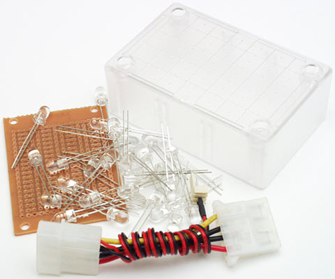
In this picture - LEDs, veroboard, a box, and a power connector cable.
First up, of course, are the LEDs. You'll need some.
Your LEDs must be identical, if you want simplicity of design. You can have a light with multiple different flavours of LEDs if you like, and do all sorts of fancy switching tricks as well. But if you do, each flavour of LED should be on a separate circuit, in parallel with the others, with its own current limiting resistor.
I made an all-red-LEDs light, using Jaycar's ZD-1777 LEDs. They list for $AU1.45 each, for quantities of more than 25.
If you're building a red case light, you'll want more than 25 LEDs; the higher up the spectrum you go the more you'll pay per LED, but the fewer LEDs you'll need, thanks to the way the human eye perceives light.
Don't buy exactly as many LEDs as you think you'll need. Get a few spares. Especially if this is your first attempt at this sort of thing.
The box I used is Jaycar's HB-6005 clear project box, which costs only $AU2.95. Its frosted finish gives a nice diffuse light.
The cable-thing in the above picture is a PSU-to-three-pin adapter, which comes with various CPU coolers to allow people to run the CPU cooler fan in computers with no three pin headers on the motherboard. There are only two wires going to the fan connector, but they're all you need; they're +12V and ground. The third wire in a three-wire lead is the fan tachometer connection.
Hack apart one of these fan connectors and you get two wires terminated with neat-o pins that are about the right size for poking into a circuit board hole. And they're pre-wired to that pass-through four-pin connector, ready to connect to your computer PSU.
You can buy computer power connectors separately and wire 'em up yourself, of course. You could put a drive power receptacle on the side of your caselight's enclosure, or just hard-splice its supply wires into a PSU lead. But this is a straightforward solution, particularly when you consider that bare computer plugs and sockets can be a bit tricky to find.
You'll also need an appropriately rated resistor to suit whatever array you intend to make. Resistors are very cheap and available in a wide range of power ratings and values.
What do you attach all of the components to? Well, if you've got time on your hands, you can etch yourself a beautiful circuit board. If you're using Luxeon lamps, you'll probably have few enough components to deal with that you won't really need a board at all.
If you're using 5mm LEDs and you're not a raving perfectionist, though, you'll use...
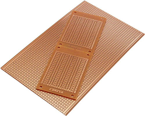
..."veroboard". This is ordinary single-sided circuit board with a pre-applied multi-purpose copper pattern on it. It makes it quite easy to create simple circuits, like an LED array. It probably isn't made by Vero Electronics any more, but "veroboard" is a trade name that's stuck. It sounds better than "perforated stripboard prototyping medium".
If you want to make a really humungous LED array then you'll want a large-ish sheet of veroboard, like the big one in the above picture. The thing sitting on top of that, though, is Jaycar's HP-9556 "Ultra Mini" veroboard. This is actually two identical snap-apart boards, and it costs a big $AU3.80 for the pair.
If you're not confident about your resistor-picking and LED-soldering abilities, by the way, do a dry run with ordinary low intensity LEDs, which you can get for less than 15 Australian cents each if you buy a bulk pack of a hundred. These LEDs aren't bright enough to make it worth putting them in a box and trying to light anything up with them, but they work in basically the same way as their more expensive high intensity brethren, and veroboard's cheap enough that there's no need to even bother removing them when you've finished fooling around. Just get another board.
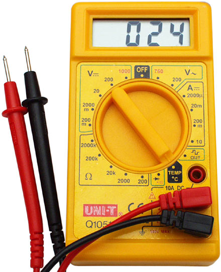
Also, get a multimeter. A $AU15 cheapie like the one in the above picture will be fine. Without one, you're left crossing your fingers and hoping that your LEDs are running at the current you think they are.
Now, the list of things you don't have to have, but which help.
A desoldering doodad of some sort. Unless you're naturally perfect, you will need to unsolder things now and then. It's much easier to do that, and to re-use the spot where the removed component was, if you've got something with which to remove the excess solder plugging the hole.
"Solder wick" is woven copper ribbon that sucks up molten solder. Spring-action solder suckers are also popular, and inexpensive.
While you're at it, get a second multimeter - or one fancy one with two sets of inputs. It's nice to have one meter in series with your LED array, telling you the current it's drawing, and another one across its inputs, telling you what voltage it's seeing. With two meters, you can watch what happens as the LEDs warm up, the current rises, and the voltage across the array falls. It's a blast. Seriously. Stop looking at me like that.
Got more spare money? Oh, good. Spend it on a variable-voltage power supply. For electronic-testing purposes, bench supplies with variable voltage and variable current are great; you can tell them not to supply more current than whatever you know is safe for the thing you're playing with. That's been experimentally proven to greatly reduce the number of friodes you'll produce.
Even a simpler supply with no current limiting is better than the fixed voltage from your PC. You can start it at a very low voltage and gently goose it up, watching the current draw on your series-connected multimeter, and stopping before anything can fry. Without such a setup, you can't easily test a half-built LED array.
For easier circuit board assembly, an adjustable vise like the Panavise Junior I used (Dick Smith Electronics have them for $AU30, catalogue number T4740) is also handy.
Laying it out
It's perfectly possible to just plunge into making an LED array - it's not like it's a time machine, or anything. The basic idea is pretty simple.
If I were you, though, I'd at least make sure I knew the rough board arrangement I was aiming for, and checked to make sure that every LED string started on a positive rail and ended on a negative one. Minor stuff like that.
If I wasn't writing an article about doing this, my layout sketch would have been a very back-of-a-beer-coaster sort of thing. But I am, so it isn't:
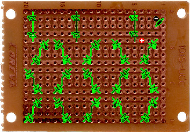
I decided on an array of 18 strings of two LEDs, which fit quite comfortably on this little board.
The red and black circles are where the power wires connect; note how the black one is on one of the little not-connected-to-anything two-hole islands, and is linked to the track I'm using as the positive rail by the array's current limiting resistor. It doesn't matter where the limiting resistor is in the circuit, as long as it's in series with the LED array.
With strings of only two red LEDs, I only needed a roughly four volt power supply for this array. So if I ran it from 12 volts, I'd need a current limiting resistor with a value of about 22 ohms. But it'd need to be able to handle the roughly 360mA I wanted to flow through the 18 20mA LED strings, and that meant it'd need around a three watt rating.
That's a rather chunky resistor, even if you can find an actual three-watter, and don't have to opt for a five watt wirewound. And I didn't want 2.88 watts of heat coming just from the resistor, plus the heat from the LEDs themselves, inside the sealed box.
So I rewired the power connector to connect to the five volt line from the PSU (the red wire) rather than the 12 volt (the yellow wire). Now the resistor only had to drop about one volt, instead of about eight. Sticking with the standard formula:
(5-4)/0.36=R
...gave a resistor value of about 2.8 ohms, and only 0.36W power dissipation, which is much more reasonable.
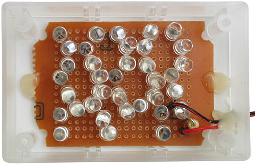
Putting it together
An LED array is a simple circuit. There may be a lot of components on the board, but you're just doing the same thing over and over.
Insert LED, make sure long leg is at the positive end, trim legs to length, solder.
I used a cut-clinch-and-burnish tool to cut the component legs off and smash them flat against the board, which effectively stops the LEDs falling off the board before you solder them. You can also, of course, solder and then trim, but that weakens the solder joint a bit.
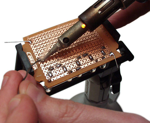
You don't need to be a soldering artiste to get it right, here. Make sure you don't bridge tracks that you don't mean to. Don't use a monster iron that'll lift the copper off the board. Take your time. Try not to breathe the lead vapour.
Don't worry about getting all of the LEDs lined up perfectly; you want a somewhat diffuse light anyway, and a frosted-plastic project box will hide any higgledy-piggledy component placement.
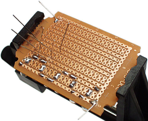
Note, by the way, the temporary contact wires tacked to the corners of the board in the above picture. They let me easily alligator-clip it to my bench supply to check it. They also let me test the completed array before I'd put its limiting resistor on.
Doing that showed me that, when it was cold, the array drew 234mA at 4.1 volts (2.05 volts across each of the LEDs in all of those 2-LED strings). Which was fine. When it warmed up, though, it drew almost 300mA at only 2.8 volts. There's that thermal runaway problem for you; if the array had still been provided with four volts, LEDs would be popping.
A bit of twiddling revealed that about 3.85V was a good input voltage to keep the LED strings at around 20mA each even when warm, which was where I wanted them to be. From a 5V supply, the resistor calculator formula worked out at 3.2 ohms with those numbers. 3.3 ohms is a standard resistor value and gave me a little extra safety room, so that's the resistor I used.
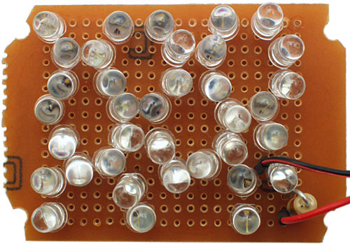
And here's the result.
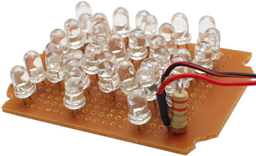
The glamour-shot version.
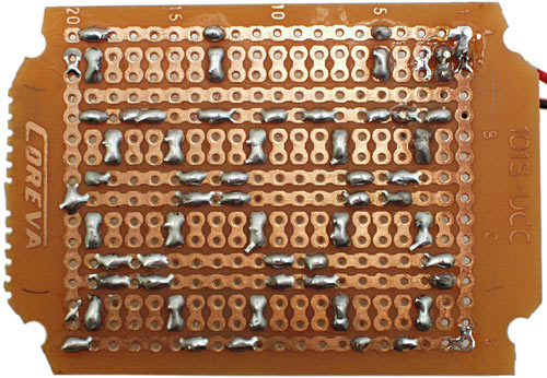
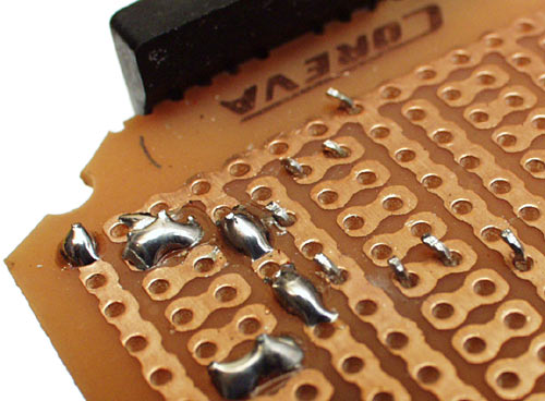
And the back of the board. Note the clipped-off corners, to get the board to fit in the little project box.
Before you attach your power wires to the board, by the way, remember to thread them through a hole you've made in your project box. Poke the hole with your hot soldering iron if you're using an all-clear box; the clear plastic is likely to split if you try to drill it.
Plus, melting holes is fun.
A couple of dabs of hot-melt glue to hold the board down and provide strain relief for the cable, and it's time to screw on the lid.
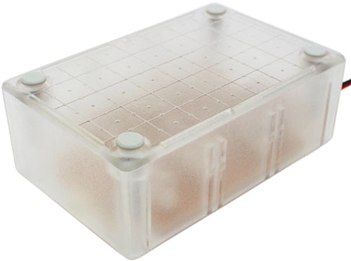
Et voila.
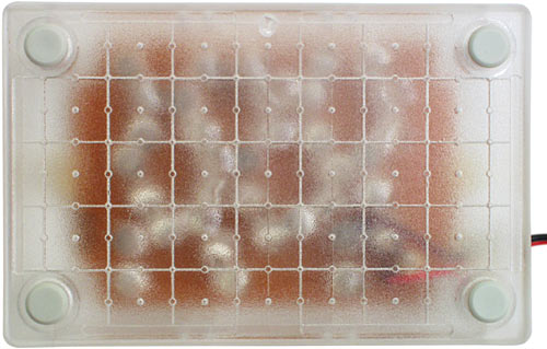
The frosted lid works well as a diffuser.
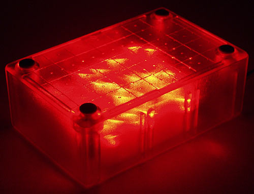
The smoke test.
I wrapped the caselight in a blanket and left it running for a while; it peaked at 370mA. That's only 20.6mA per LED, about 450mW being dissipated by the resistor, and 1.85 watts total draw. Bewdy.
Oh, yeah. Does it work?
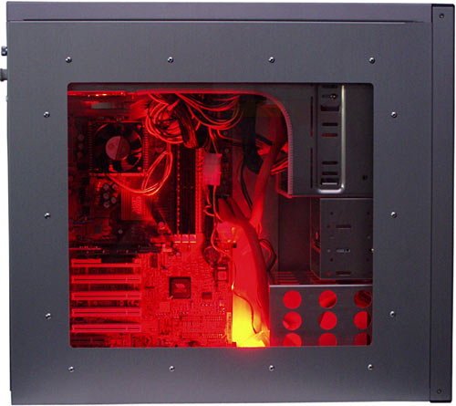
Yes. Yes it does. It's quite bright enough to make the case glow impressively in a normally lit room.
It's easy to mount a little light like this with double-sided tape in various spots in the average case. It's certainly easier than mounting a neon tube.
At 20mA, the quoted life span for a common-or-garden high intensity LED is around 100,000 hours. That's over eleven years of continuous operation. If you only have your computer turned on for, say, eight hours a day, then you can triple that figure to get the light's service life.
At the end of their official life span, LEDs don't go ping and stop working, like an incandescent bulb. If you don't overdrive them, they just get dimmer and dimmer over a quite long period of time.
So I wouldn't be surprised if this thing were still be bright enough to use as a reading lamp after fifty years of continuous use.
The parts cost about $AU60. Less, actually, because the LEDs were on special. That's not bad life per dollar.
8051 Starter for embedded systems....
having problem Using 89C51 ...
low memory (ROM)...4k only 128byte RAM
Difficulty in burning the IC ...
More complex programmers....
So here is a solution.....
Start using 89S series...
eg. 89S52 (8kb ROM 256 byte of RAM space) will be sufficient for most of you...
all ISP using 4 wire interface as is available with AVR
that is... only 4 wires ... RESET,,,,MOSI,,,MISO,,,,& SCK
also it is available at more or less at the same cost...
(ATMEL knows what all wants..)
CIRCUIT 1:
- Designed for new ISP chips, 89S51, 89S52, and 89S53, 40-pin DIP,
- In System Programmable (ISP) through the 6-pin header and a jumper, (no need external programmer),
Printer PORT ---- 89S51 / 89S52 or similar
pin 6 SCK
pin 7 MOSI
pin 9 RST
pin 10 MISO
Pin 18 - 25 GND
(TESTED)

Make your own ISP cable for the circuit board
OR
connect directly to IC on a breadboard
OR
connect on your own made IC board on general Purpose PCB]
SOFTWARE to be used :: ISP-Flash Programmer Ver3.0a available at
http://www.kmitl.ac.th/%7Ekswichit%20/IspPgm30a/ISP-30a.zip
CIRCUIT 2 (TESTED)
Circuit using Buffer 74HC541 (similar to 74HC244) compatible to STK200
 6 wire interface (5 wire & a GND pin)
Parallel PORT pins to be used
PIN 5
PIN 6
PIN 7
PIN 9
PIN 10
PIN 18-25
Software used :: SAME ISP-Flash Programmer ver3.0
for extra details go to
Circuit 1:
http://www.kmitl.ac.th/~kswichit%20/tahan/boards51/Board%20S51.htm
Circuit 2:
http://www.kmitl.ac.th/%7Ekswichit%20/IspPgm30a/ISP-Pgm30a.html
else contact me...
*** NOTE :: connect + VCC & GND to 8051 .....
TESTED
Basics of AVR for embedded starters..
If you are having any problem with AVR microcontroller burner ....
Not able to get one....
If your PC have a parallel port...
then..
NO need to buy any STK500 or similar....
just....
make your own programmer.....
as simple as possible ....
a) Only 5 wire interface... ( 4 basic wires & one ground cable)
using BSD programmer.....
Just connect pin no..
Parallel Port --- AVR
7 --- RESET
8 --- SCK
9 --- MOSI
10 --- MISO
18-25 ---- GND
Software Used :: AVR dude windows based programmer
b) Use a buffer / driver for the programmer (STK 200 dongle)
(click on above link for the larger image of circuit)
only one IC 74HC244 required
the circuit can be made on a bread board... or on normal PCB
Software used :: PONYPROG on the same website www.lancos.com
* circuit of AVR STK200 dongle is also available on www.electronicsforu.com
or use google search for old Kanda or ISP circuit or STK200 dongle
Both the programmers have been made & tested.
for any help contact me
Wednesday, May 7, 2008
Learn Core Computer Secrets.
For all computer secrets ....and related information ....
just go to....
http://learncomputersecrets.blogspot.com/
find all critical updates on this blog...
& necessary links for similar information....
Subscribe to:
Comments (Atom)

